Logic Gates
From Coder Merlin
Within these castle walls be forged Mavens of Computer Science ...
— Merlin, The Coder
Introduction[edit]
A logic gate is an idealized or physical device implementing a Boolean function; that is, it performs a logical operation on one or more binary inputs and produces one or more binary outputs.
Symbols[edit]
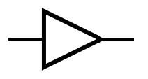
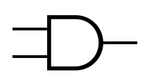
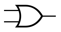
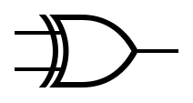
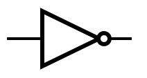
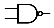
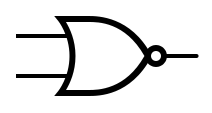
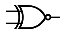
The table below provides the symbols that are used to represent common gates.
Additionally, a multiplexer is a device which selects from digital inputs and forwards the signal to a single output line. Given inputs, there are selector pins. Conversely, a demultiplexer forwards the signal from a single line to one of multiple outputs.
| Formal Name | Abbreviated Name | Symbol | Gate | Truth Table | ||||||||||||||||||||||||||||||||||||||||
|---|---|---|---|---|---|---|---|---|---|---|---|---|---|---|---|---|---|---|---|---|---|---|---|---|---|---|---|---|---|---|---|---|---|---|---|---|---|---|---|---|---|---|---|---|
| Multiplexer | MUX | 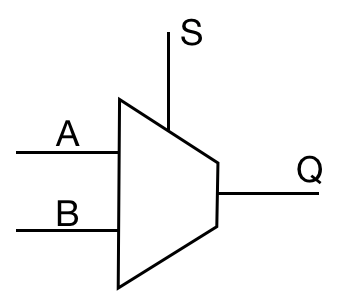
|
| |||||||||||||||||||||||||||||||||||||||||
| Demultiplexer | DEMUX | 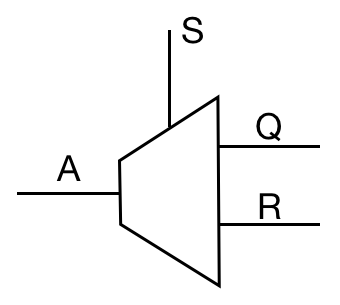
|
| |||||||||||||||||||||||||||||||||||||||||
| Coming Soon | |
|

