Difference between revisions of "Logic Gates"
From Coder Merlin
| Line 1: | Line 1: | ||
== | == Introduction == | ||
A logic gate is an idealized or physical device implementing a Boolean function; that is, it performs a logical operation on one or more binary inputs and produces one or more binary outputs. | |||
== Symbols == | |||
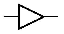
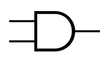
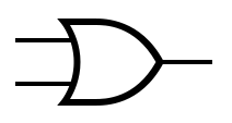
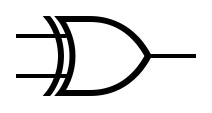
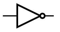
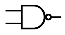
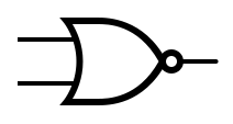
The table below provides the symbols that are used to represent common gates. | |||
{| class="wikitable" | {| class="wikitable" | ||
| Line 173: | Line 176: | ||
|- | |- | ||
| 1 || 1 || 1 | | 1 || 1 || 1 | ||
|} | |||
|} | |||
Additionally, a '''multiplexer''' is a device which selects from <math>n</math> digital inputs and forwards the signal to a single output line. Given <math>n</math> inputs, there are <math>log_2 n</math> selector pins. Conversely, a '''demultiplexer''' forwards the signal from a single line to one of multiple outputs. | |||
{| class="wikitable" | |||
! Formal Name | |||
! Abbreviated Name | |||
! Symbol | |||
! Gate | |||
! Truth Table | |||
|- | |||
| Multiplexer | |||
| MUX | |||
| <math>{A \cdot \overline{S}} \lor {B \cdot S}</math> | |||
| [[File:Multiplexer-ABSQ.png ]] | |||
| | |||
{| class="wikitable" style="text-align: center;" | |||
!colspan="3"| Inputs | |||
! Outputs | |||
|- | |||
! <math>S</math> | |||
! <math>A</math> | |||
! <math>B</math> | |||
! <math>Q = {A \cdot \overline{S}} \lor {B \cdot S}</math> | |||
|- | |||
| 0 || 0 || 0 || 0 | |||
|- | |||
| 0 || 0 || 1 || 0 | |||
|- | |||
| 0 || 1 || 0 || 1 | |||
|- | |||
| 0 || 1 || 1 || 1 | |||
|- | |||
| 1 || 0 || 0 || 0 | |||
|- | |||
| 1 || 0 || 1 || 1 | |||
|- | |||
| 1 || 1 || 0 || 0 | |||
|- | |||
| 1 || 1 || 1 || 1 | |||
|} | |||
|- | |||
| Demultiplexer | |||
| DEMUX | |||
| <math>{A \cdot \overline{S}} \lor {B \cdot S}</math> | |||
| [[File:Demultiplexer-ABSQ.png ]] | |||
| | |||
{| class="wikitable" style="text-align: center;" | |||
!colspan="2"| Inputs | |||
!colspan="2"| Outputs | |||
|- | |||
! <math>S</math> | |||
! <math>A</math> | |||
! <math>Q = {\overline{S} \cdot A}</math> | |||
! <math>R = {S \cdot A}</math> | |||
|- | |||
| 0 || 0 || 0 || 0 | |||
|- | |||
| 0 || 1 || 1 || 0 | |||
|- | |||
| 1 || 0 || 0 || 0 | |||
|- | |||
| 1 || 1 || 0 || 1 | |||
|} | |} | ||
|} | |} | ||
{{ComingSoon| | {{ComingSoon| | ||
Revision as of 17:37, 16 July 2019
Within these castle walls be forged Mavens of Computer Science ...
— Merlin, The Coder
Introduction[edit]
A logic gate is an idealized or physical device implementing a Boolean function; that is, it performs a logical operation on one or more binary inputs and produces one or more binary outputs.
Symbols[edit]
The table below provides the symbols that are used to represent common gates.
Additionally, a multiplexer is a device which selects from digital inputs and forwards the signal to a single output line. Given inputs, there are selector pins. Conversely, a demultiplexer forwards the signal from a single line to one of multiple outputs.
| Formal Name | Abbreviated Name | Symbol | Gate | Truth Table | ||||||||||||||||||||||||||||||||||||||||
|---|---|---|---|---|---|---|---|---|---|---|---|---|---|---|---|---|---|---|---|---|---|---|---|---|---|---|---|---|---|---|---|---|---|---|---|---|---|---|---|---|---|---|---|---|
| Multiplexer | MUX | 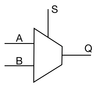
|
| |||||||||||||||||||||||||||||||||||||||||
| Demultiplexer | DEMUX | 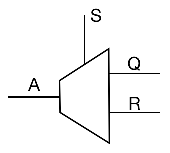
|
| |||||||||||||||||||||||||||||||||||||||||
| Coming Soon | |
|

