
Logic Composition
Prerequisites[edit]
Background[edit]
Logic gates can be cascaded in the same way that Boolean functions can be composed, allowing the construction of a physical model of all of Boolean logic.
Three-Input And Gate[edit]

Consider this three input AND gate internally constructed of two, two-input AND gates. The truth table for this composition is:
| Inputs | Outputs | ||
|---|---|---|---|
| 0 | 0 | 0 | 0 |
| 0 | 0 | 1 | 0 |
| 0 | 1 | 0 | 0 |
| 0 | 1 | 1 | 0 |
| 1 | 0 | 0 | 0 |
| 1 | 0 | 1 | 0 |
| 1 | 1 | 0 | 0 |
| 1 | 1 | 1 | 1 |


 Helpful Hint
Implication Gate[edit]

Consider this IMPLY gate internally constructed of a NOT gate and an OR gate. The truth table for this composition is:
| Inputs | Outputs | |
|---|---|---|
| 0 | 0 | 1 |
| 0 | 1 | 1 |
| 1 | 0 | 0 |
| 1 | 1 | 1 |


Implication is formally indicated by a formal arrow, i.e. , meaning, if p is true, then q is also true. As an example, consider the implication, "if it's raining then I'll carry my umbrella". There are four cases, only one of which yields false:

| Raining | Equipped with Umbrella | Evaluation of Statement |
|---|---|---|
| No | No | true |
| No | Yes | true |
| Yes | No | false |
| Yes | Yes | true |
Experiment[edit]
This exercise relies on an external website which will enable you to easily experiment with logic gates and form various compositions with the components. The links on this wiki page will preload the relevant gates currently under discussion. For best results, open the links in a separate window so that you can continue to read the wiki while you experiment.
- The "L" indicates a Low voltage which usually represents zero or false
- The "H" indicates a High voltage which usually represents one or true
- The layout flows from left to right.
- Inputs will be leftmost and output will be rightmost.
- Clicking on an input will toggle the input from Low to High or from High to Low
- When an input is changed, the result will instantly impact the rest of the digram.
Input, Output, and an Inverter[edit]
Click on the image to the right ("Wire and Inverter") and open the link in a different window, then return to the wiki: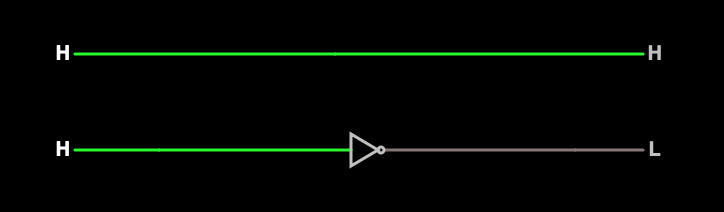
- Click on the leftmost (input) H in the top diagram which simply represents a wire.
- What happens to the H?
- Does the color of the wire change?
- How is the output impacted?
- Click on the leftmost (input) H in the bottom diagram which represents an inverter.
- What happens to the H?
- Does the color of the wire change?
- How is the output impacted?
AND Gate[edit]
Click on the image to the right ("AND Gate") and open the link in a different window, then return to the wiki: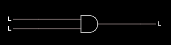
- Click on the top L input.
- What happens to the top L?
- What happens to the output?
- Click on the bottom L input.
- What happens to the bottom L?
- What happens to the output?
- Click several more times on the inputs until you're able to consistently predict the output.